Project 9 : Electric Vehicle


Electric bicycle model

Electric car model
Speed and odometer

Inside controller box

Video on demand
Descriptions:

It is a green project using an incentive grant project to design an electric bicycle for testing and running. It consists of 48V BLDC motor, 12V batteries (4 in series), the motor contoller and the PIC microcontroller. The input for BLDC is 48 Vdc battery. The motor controller converts this voltage to a powerful 3-phase AC power (about 500W) for driving BLDC using an inverter circuit. The BLDC motor has 3 hall sensors built inside it to sense the motor position.  

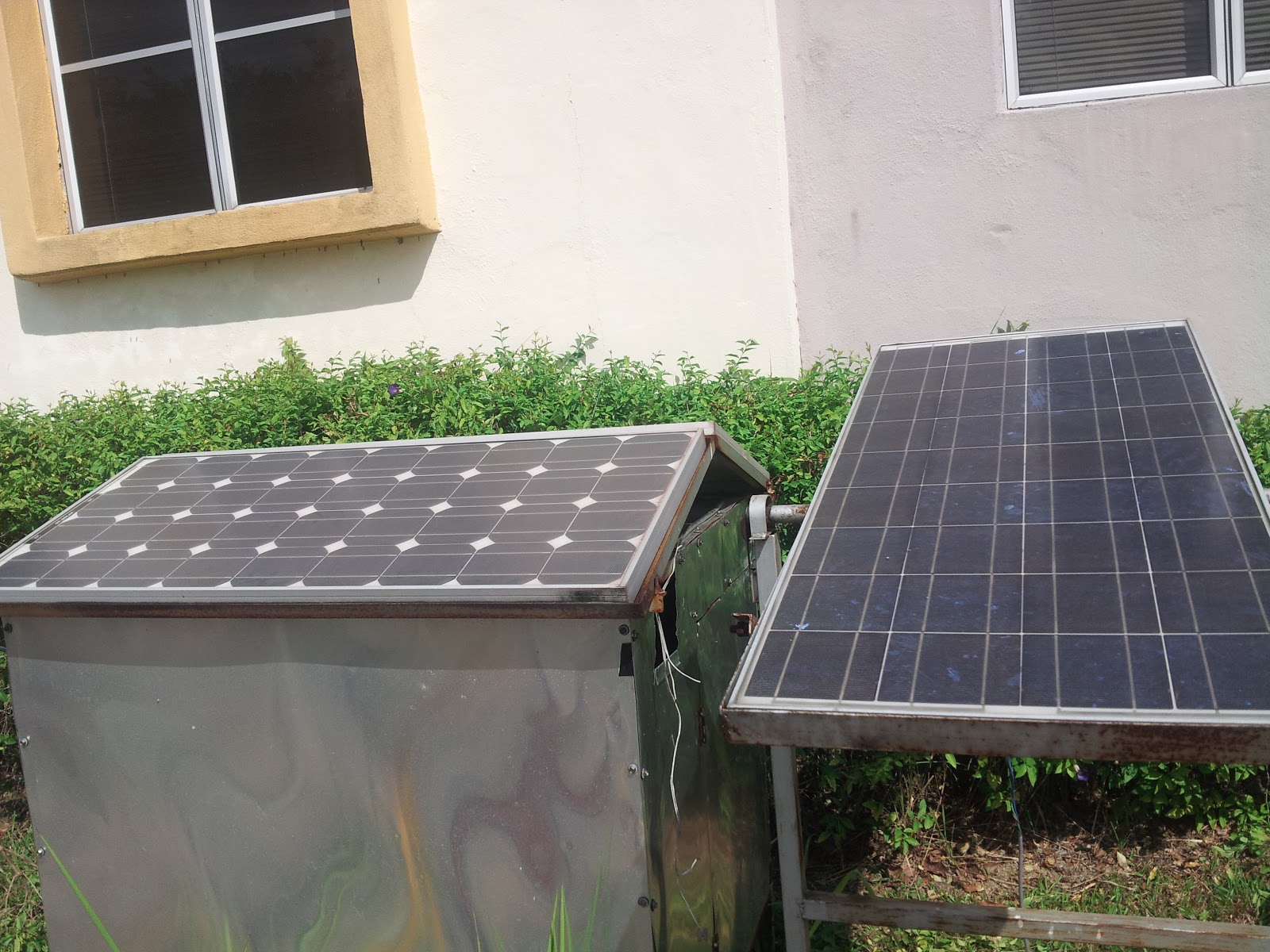
A hand throttle and hand brake is used to control the speed. The maximum speed is 35km/h. With 12V,7Ah batteries, you may drive the bicycle for half an hour before need to be charged again. The charging process is based on 48V-based voltage using solar panel (solar charging station at 52V, 3 units of panels) or may be plugged through home socket output (240Vac). The motor has special features built using PIC microcontroller i.e speedometer and odometer. It is also equipped with a smart protection system using a gyrometer to avoid the system from being stolen.

Prinsip operasi

Sebuah projek membangunkan sebuah basikal elektrik. Sistem menggunakan voltan 48V, motor jenis BLDC(brushless DC motor) yg mana inputnya bekalan DC (bateri 48V) ditukar kpd AC 3 fasa utk menghasillkan power yg cukup besar (sekitar 500W bg menggerakkan penunggang). Sistem dilengkapi dengan sebuah meter indikator digital yg dibina berasaskan PIC utk memaparkan status kenderaan (STOP, Gear 1,2,3,4), speedometer (km/h) dan mileage (m). Sistem juga dibina alat pencegah kecurian berasaskan accelerometer dan alat ini dikawal oleh remote control.

Throttle tangan digunakan utk memecut kenderaan. Kelajuan maksimum direkodkan 35km/h. Ketepatan halaju dan mileage telah disahkan dgn penggunaan GoogleEarth bg merekod track perjalanan. Sistem bekalan bateri 48V dicas menggunakan tenaga solar (charging station). Juga boleh menggunakan plug dr rumah (240V) dan memerlukan penukar voltan turun.

Projek 8 : TEG Stove Charger

Backside stove

Stove
System installation
Stove charger

Video on demand

Descriptions:
This project has been awarded a gold medal in the ITEX convention. It is a stove charger used to charge your handphone battery, desk lamp or LED light. The heat we prodecud from cooking process is converted into electricity using thermo electric generator TEG. The number of electricity produced depends on the temperature difference between the two side of TEG. One side is cooled with air while another side is attached to the heat. The bigger the difference, the greater electricity we produced.

The electricity then is fed into a charging circuit controlled by a PIC microcontroller. The controller also displays the charging rate and the charging voltage for user to monitor this process. A number of 6 TEGs are used in series to produce 12-17 V that is similar to solar panel voltage. The controller can be programmed to charger 5V batteries or 12 V batteries.

Prinsip operasi

Projek ini telah memenangi pingat emas di ITEX (Innovation and Technology Excibition) May 2013. Satu pencapaian yang membanggakan bagi peserta yang terlibat. Sebuah projek menggunakan dapur masakan (stove) utk menghasilkan tenaga haba yg ditukar kpd tenaga elektrik melalui penggunaan TEG(thermo electric generator). Perbezaan haba (delta T) antara 2 sisi permukaan menghasilkan satu julat voltan/arus yg digunakan utk mengecas bateri handphone. Selain itu boleh digunakan utk lampu LED bilik tidur dsbnya. Litar PIC digunakan utk memaparkan charging voltage dan status charger. Sejumplah 6 TEG digunakan secara siri utk menghasilkan voltan open circuit sbnyk 12-17V sesuai dgn kadaran voltan yg hampir sama dgn PV(solar panel). Litar pengecas bateri akan menurunkan voltan TEG kpd nilai yg sesuai utk pengecasan bateri (14V utk bateri 12V) dan (5V utk bateri handpone).

Project 7: Jig Class A


Front view 

Side view

System test

Video on tape

Descriptions:

This is an industrial project proposed by one company to place a sticker automatically for motorola walkie-talkie casing. A spesified slot has been provided for production operator to place the walkie-talkie. An infrared sensor will detect the presence of walkie-talkie, send a signal to PIC to rotate a stepper motor used to bring down the sticker on that casing until it detects a specified lenght of sticker. A servo motor is attached to the jig body to stamp the sticker on the casing. When finish stamping the sticker, the stepper motor continues to rotate until it detects new stop sensor. The process continues as the production operator put a new casing in the provided slot.

Prinsip operasi

Ini sebuah projek drpd industri digunakan untuk menampal sticker secara automatik ke atas casing walkie-talkie. Operator perlu meletakkan casing walkie-talkie pd slot yg disediakan,sejenis sensor infarared akan mengesan kehadiran walkie-talkie. PIC arahkan sebuah motor stepper utk memusingkan lilitan sticker dlm masa yg sama sebuah motor servo digandingkan dgn jig digunakan utk melekatkan sticker pd casing.  Proses ini berterusan setiap kali operator meletakkan casing yg baru. Dlm program, jarak pergerakan motor stepper dikawal mengikut  panjang sticker tsbt. Projek boleh diupgrade dgn menambahkan slot sensor utk mengesan kedudukan  bg satu sticker.

Project 6: Solar SCADA oscilloscope

 Solar panels
Solar Charge Controller

 PIC Board
 Interfacer board
 SCADA 1
SCADA 2
Descriptions:

The SCADA (supervisory control data acquissition) oscilloscope is built using visual basic software to display the instataneous value of solar panel voltage. The SCADA program is equipped with some control buttons to start,stop and record the solar voltage. The recording time can be set through these buttons. The voltage from solar panel is hooked up to solar charge controller for charging purpose. Sealed lead acid(SLA) or AGM batteries are used as free maintainance batteries for storing energy from solar.

PIC microcontroller is used to read the voltage from solar panel using voltage divider circuit and ADC program. The PIC then translates this signal to be displayed on computer screen. The data are send through serial cable or using USB to UART converter. Two readings recorded from solar panel, one is diplayed as number via LCD, another one as image via computer screen. 

Prinsip operasi
Asas prinsip operasi iaitu sistem akan memaparkan osiloskop pada komputer untuk menunjukkan voltan semasa solar panel. Satu software visual basic dibangunkan untuk menerima data voltan dari solar panel dan PIC. PIC akan membaca data ini melalui voltage divider circuit dan menghantar data tersebut ke komputer melalui serial cable dan memaparkannya pada skrin. Didalam program visual basic, pengguna boleh memilih corak paparan dan setting masing2 mengikut kehendak pengguna. Sbg contohnya membuat setting corak paparan data(jenis dot, garis, bulatan dsbnya) atau memaparkannya dalam bentuk nilai. Julat tempoh masa paparan boleh diprogram melalui visual basic  samada seminit, sejam, sehari atau sebagainya. Data2 ini boleh direkod dan diletakkan dalam satu file (notepad/ excel) utk diakses oleh pengguna.

Selain dari voltan, parameter lain yg boleh dipaparkan adalah arus dan kuasa.  Sistem ini dikenali sbg SCADA (supervisory control data) dan digunakan secara meluas utk membuat analisis atau pemantauan yg mana masa sbg pembolehubah utamanya.
 

Project 5: Dot Matrix Digital Clock


Arrow sign display

Text display
 

 Visual basic interface
 
 Clock and Date Display
 
Descriptions:

The concept of digital clock is to display the real time and date using dot matrix LED display (8X16). A visual basic software interface has been developed to send the clock and date data from computer to microcontroller. The microcontroller then reads this data through serial cable before displaying as texts and numbers. In visual basic programming, the users can build their own GUI (graphical user interface) to set or change any parameters of the clock and date. They can even create their own pattern like an arrow sign etc.

Prinsip operasi
Asas prinsip operasi iaitu sistem jam digital akan dipaparkan pada paparan dot matrix (8X16). Satu software visual basic dibangunkan untuk menghantar data clock dari komputer ke PIC. PIC akan membaca data ini melalui serial cable dan memaparkannya pada 8X16 Dot Matrix LED. Didalam program visual basic, pengguna boleh memilih corak paparan dan setting masing2 mengikut kehendak pengguna. Sbg contohnya membuat setting pada jam 1.00 PM satu suara peringatan akan dikeluarkan dari speaker komputer. Suara ini boleh dirakam mengikut kehendak pengguna.

Selain drpd jam digital, PIC juga boleh diprogram untuk mengeluarkan paparan2 tertentu mengikut kehendak pengguna bergantung kpd kemampuan pattern yg boleh dijanakan oleh dot matrix LED.
Sbg contohnya arah anah panah spt gambar diatas.

Project 4: RFID Door Locking


 Project setup
Controller on the door 
System installation

Descriptions:

The principal of the project is to build a smart access system for door using RFID. The users need to use authorized card (Mifare card) to access that door or room. The card is operated at 125kHz or 13.6 Mhz depend on the RFID reader spec. Each card has its own identity number (ID) and can be programmed into microcontroller. This ID will be kept in the microcontroller memory and can be called anytime. The number of cards that can be installed to the system depend on the number of microcontroller memory. The bigger it has the higher ID may be installed. Only authorized person which registered ID is allowed to use the system.

The PIC will send a signal to unlock the solenoid/magnetic lock once it senses a correct ID. In this system, any Mifare cards including Touch n Go card (TnG) can be used as it has the same number of ASCII characters inside the card. The system may be upgraded by adding RF controller (remote) if the users decide to open the door from far without touching the reader.


Prinsip operasi
Asas prinsip operasi iaitu pengguna perlu menggunakan kad/tag untuk mengaktifkan RFID reader.
Setiap kad/tag mempunyai ID tersendiri dimana ID ini akan disimpan dalam memori PIC. Hanya kad berdaftar shj yg dibenarkan utk akses kpd pintu ini. Frekuensi reader yg digunakan adalah 125kHz/13.6MHz. PIC akan scan data2 ID yg dihantar melalui reader ke PIC. PIC akan mengarahkan locking system utk buka/tutup bergantung kpd akses yg telah ditetapkan.

Jenis locking system yg digunakan adalah solenoid/magnetick lock. Kad Touch N Go (TnG) juga boleh digunakan untuk sistem ini. Projek ini boleh diupgrade dgn menambah komponen RF (remote controller) jika pengguna ingin membuka pintu dr jauh tanpa meletakkan kad ID kpd reader. 

Project 3: Smart Kitchen Fire System


 Project setup
 
Schematic drawing

Layout drawing
 
 
Video on demand
Descriptions:


The idea of a smart kitchen project is to develop an in house smart system for protecting our kitchen from danger when fire takes place, smoke or temperature rise. The project focuses on protecting our gas stove from exploding in case certain unnecessary situations happen. To implement this project, 3 types of sensor are being used in this system i.e fix heat temperature sensor, programmable temperature sensor LM35D and smoke detettor. The fix temperature sensor is a normally closed sensor which is rated at 50 to 57 degree celcius. Meanwhile the programmable temperature sensor LM35 can be programmed and its temperature is displayed in LCD. The smoke detector senses if there is any smoke produced by fire.

The PIC microcontroller will sense any one of these 3 sensors. In a normal mode, LCD will display "Normal Mode" to show that situation is under control, no fire or no smoke. In case a fire set in the kitchen, or temperature reaches 50 degree, or smoke appears in the kitchen, the controller will sense an early warning (set by programmable sensor at around 45 to 50 degree), thus producing an alert system i.e LED and buzzer to beep for 3 times. The LCD status display will turn to "Fire Alarm" and blink this alert for 3 times.

During the fire, an infrared sensor placed to the cooker will sense the position of cooking knob. If the cooking knob is used or the cooking process is running, the controller will send a signal to a stepper motor to turn clockwise so that the cooking knob is shut off. Only then, the cooking process is ended automatically without the user needs to turn it OFF manually. A switch is also provided for the user to deactivate the buzzer sound if he accidently trigger smoke (due to smoking) in the kitchen. Stepper motor is used in the system to control the cooking knob because it has high torque and power.
Asas Prinsip operasi iaitu terdapat 3 jenis sensor yg digunakan iaitu jenis fix heat temperature(57 darjah celcius), temperature IC LM35 ( diset over 50 darjar celcius) dan smoke detektor.  PIC akan mengesan mana2 satu drpd 3 jenis sensor ini sblm mengaktifkan penggera kebakaran. Pada keadaan normal LCD akan memaparkan bacaan suhu semasa dan text “Normal Mode” dipaparkan.  Jika PIC mengesan suhu  awal kebakaran (sekitar 50 – 57 darjah celcius), atau mengesan asap di dapur, maka controller akan aktifkan buzzer sebanyak 3 kali (LCD juga akan paparkan suhu semasa dan text “Fire Alarm” blinking sebanyak 3 kali).

Jika semasa kebakaran dapur digunakan (aktiviti memasak), sensor infrared akan mengesan kedudukan ON tombol laras kekuatan api, maka controller akan arahkan motor untuk memutar tombol laras api tadi ke arah kiri ke kedudukan OFF. Maka dapur masakan akan dipadamkan secara automatic apabila berlaku kebakaran. Suis SW1 boleh digunakan utk matikan bunyi buzzer semasa berlaku kebakaran. Motor yg digunakan untuk memacu dapur dr jenis stepper motor. Suis SW2 boleh digunakan jika jenis motor stepper lebih besar digunakan.

Project 2: Home Autolocking System


Project setup
 
The system may be installed at house/office. When the system is activated for the first time, the user needs to key in the password. PIC microcontroller will keep the chosen password inside its memory. To use the system, the user will press the correct codes according to the chosen password to open the door. If the user fail to key in correctly for three times, the system will activate its security sytem by beeping a buzzer.
 
The system is also equipped with a magenetic sensor to detect any person who tries to intrude the house. A snapshot camera is attached to the microcontroller to snap that person. An electric bolt is used as a locking element which has the same function with solenoid/megnetic lock. If there is power failure to the system, the locker will open itself.

 
Orcad schematic design of controller and motor driver.

PCB layout design of controller and motor driver.
 
 
Video on tape 
Descriptions:

Mod manual:
Sistem ini boleh dipasang pada pintu rumah/pejabat. Apabila sistem dihidupkan kali pertama, pengguna diminta memasukkan kata laluan password dan dipaparkan pada paparan LCD. PIC akan menyimpan password tersebut didalam memorinya. Setiap kali ingin memasuki pintu, pengguna akan memasukkan password yg betul utk membolehkan pintu dibuka. Kegagalan memasukkan password yg betul menyebabkab pintu tidak boleh dibuka. Jenis locking system yg digunakan adalah jenis solenoid/magnetic lock,iaitu pintu akan terbuka jika berlaku power failure pd system.

Mod Auto:
Pintu rumah akan dipasang sejenis sensor (magnetic sensor) untuk mengesan penceroboh sekiranya pintu diceroboh tanpa menggunakan password. Apabila diceroboh, sensor akan menghantar satu data kpd PIC untuk membunyikan alarm (buzzer). Sistem juga boleh diupgrade dgn menambahkan sejenis kamera untuk menangkap imej penceroboh tadi.


Project 1: Smart Rostrum Controller


 Board under testing

 Board layout

Early test setup

Project setup consists of PIC microcontroller, rostrum, remote controller and sensors. 2 modes of control i.e auto or manual depends on the user.

In automatic mode, IR sensor is placed on rosturm to detect the appearence of paper when user stand to give a talk. PIC receives data from sensor to activate the DC motor, lift up the microphone. While lifting up, an ultrasonic sensor is used to detect the height of user and microphone. At desired height, the motor will stop once the controller reachs the targetted height. After finish giving his/her talk, the user will remove the paper and automatically the PIC orders the motor to lift down the microphone to original position.

In manual mode, the user needs to use a RF transmitter to lift up or down the microphone. The height can be controlled manually. There are 4 buttons to control the microphone, up, down, stop and speed.


Orcad schematic design of controller and motor driver.
  
PCB layout design of controller and motor driver.

Descriptions:
Mod Auto:
Apabila pengguna berdiri utk berucap, letakkan kertas/teks ucapan pd rostrum. Sejenis sensor infrared  OPB706 akan mengesan kehadiran kertas dan menghantar data kepada pemproses utama(PIC). PIC akan keluarkan satu isyarat data kepada driver motor (L293D),mengarahkan motor rostrum untuk menaikkan mikrofon keatas. Semasa naik, sejenis sensor ultrasonic akan mengesan ketinggian kepala pengguna sehinggalah pada satu jarak ditetapkan (sekitar 1.5 meter), apabila jarak tersebut telah dicapai, dianggapkan mirofon berada pada kedudukan selari dengan mulut .Kemudian sensor ini akan hantar data kpd pemproses utama(PIC) utk hentikan motor. Pengguna akan berucap apabila mirofon berada pada kedudukan selari dengan mulut . Apabila pengguna habis berucap, kertas/teks akan dikeluarkan drpd rostrum, maka sensor OPB706 td akan menghantar data kpd pemproses utama(PIC). PIC akan keluarkan satu isyarat data kepada driver motor (L293D) utk menurunkan motor sehinggala kedudukan motor sama dengan sensor infrared jenis slot. Apabila keadaan ini tercapai, satu data akan dihantar  kepada pemproses utama(PIC) utk hentikan motor.

Mod manual:
Pengguna perlu menekan button A RF transmitter 315MHz utk menaikkan motor ke jarak yang dikehendaki .  Data drpd RF transmitter akan dibaca oleh pemproses utama(PIC). PIC akan keluarkan satu isyarat data kepada driver motor (L293D),mengarahkan motor rostrum untuk menaikkan mikrofon keatas selagi mana button A ditekan. Pengguna perlu menekan button B RF transmitter 315MHz utk menurunkan motor ke jarak yang dikehendaki .  Data drpd RF transmitter akan dibaca oleh  pemproses utama(PIC). PIC akan keluarkan satu isyarat data kepada driver motor (L293D),mengarahkan motor rostrum untuk menurunkan mikrofon kebawah selagi mana button B ditekan.

INTRODUCTION

Welcome....The purposes of this blog is to show/expose some of the electronic projects developed in order to be used in teaching, FYP projects, industrial design projects and so on. The projects cover certain areas in electrical and electronic engineering including solar, wind energy, EV, sensor, digital, analogue, robotic, communication and microcontroller. With a hope that anybody who is interested in this field may learn something and give some ideas/comments on how to improve the engineering skills needed to expand their knowledge. We also accept any request for designing your own project based on your idea. Until now we have developed more than 50 projects and some of them will be portrayed here very soon. Any question can be directly commented here or emailed to eemnazir@eng.usm.my.

Salam...Blog ini bertujuan menunjukkan/mendedahkan projek2 elektronik yg tlh dibangunkan untuk tujuan pembelajaran, projek FYP, projek rekabentuk industri dll..... Projek2 tsbt merangkumi bidang2 yg ditawarkan dalam elektrik dan elektronik......antaranya areas yg dicover termasuklah elektrikal (solar,wind energy, electric vehicle), elektronik (sensor,digital,analog circuit), robotik (kawalan manipulator, minirobot), communication (RF, remote controller, RFID) dan microcontroller (PIC). Diharapkan kepada peminat2 elektrik & elektronik bolehla belajar drpd blog ini dan memberi komen balas tentang cadangan atau idea dlm mengembangkan ilmu kejuruteraan nie...Kami juga menerima tempahan rekabentuk design projek elektronik mengikut idea pengguna (custom made)... Buat masa nie lebih 50 projek telah direkabentuk dan sebahagiannya akan dipaparkan ke dalam blog dari masa ke semasa.

Sebarang pertanyaan bolehla letak pd ruangan komen atau diemailkan kpd kami eemnazir@eng.usm.my.

Sekian.
Moderator