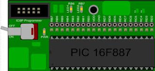
Tut 3 : 7-segment LED and Keypad

A program to press keypad and display the numbers on 7-segment LED (common-anode).

7-segment LED display
 
It is composed of 8 LEDs- 7 segments are arranged as a rectangle for symbol displaying and there is an additional segment for decimal point displaying. In order to simplify connection, anodes or cathodes of all diodes are connected to the common pin so that there are common anode displays and common cathode displays, respectively. Segments are marked with the letters from a to g, plus decimal point (dp), as shown in figure below. On connecting, each diode is treated separately, which means that each must have its own current limiting resistor.


In addition to digits from 0 to 9, there are some letters- A, C, E, J, F, U, H, L, b, c, d, o, r, t  that can be also displayed by means of the appropriate masking.

Keypad configuration
 
PBP Program

' Example program to read keypad numbers and display with 7-segment

DEFINE OSC 20                          ' using 20MHz clock oscillator
@ device hs_osc

        row1 VAR PORTD.6    'declare ports
        row2 VAR PORTD.5
        row3 VAR PORTD.4
        row4 VAR PORTD.3
        col1 VAR PORTD.2
        col2 VAR PORTD.1
        col3 VAR PORTD.0
                    
        TRISD=%11111000 'assign ports
        TRISB=0
             
     loop:
    
     Low col1:High col2:High col3          'column 1

     IF (row1==0) Then                 'if key 1 is pressed
     PORTB=%1111001
     Pause 1000
     Else
     PORTB=%1111111
     EndIF
    
     IF (row3==0) Then                     'key 7
     PORTB=%1111000
     Pause 1000
     Else
     PORTB=%1111111
     EndIF
    
     IF (row4==0) Then                     'key *
     PORTB=%0111111
     Pause 1000
     Else
     PORTB=%1111111
     EndIF
    
     High col1:Low col2:High col3            'column 2

     IF (row1==0) Then                    'key 2
     PORTB=%0100100
     Pause 1000
     Else
     PORTB=%1111111
     EndIF
          
     IF (row4==0) Then                       'key 0
     PORTB=%1000000
     Pause 1000
     Else
     PORTB=%1111111
     EndIF

     High col1:High col2:Low col3           'column 3

     IF (row1==0) Then                    'key 3
     PORTB=%0110000
     Pause 1000
     Else
     PORTB=%1111111
     EndIF
    
     GoTo loop
     End
    
You should try to write your own program for numbers "4", "5", "6" "8", "9" and symbol "#"......


Tut 2 : Blinking LED

A program to blink LED red and green on SK40C board. The delay time is set to 1 second. The blinking will repeat continously.

 
LED and current limiting resistor

LED has two ends an anode and a cathode. Connect it properly to a power supply voltage. The diode will emit light. Depending on any power supply voltage, you need to discard the current through a current limiting resistor to protect LED from burning.

PBP Program

DEFINE OSC 20                                        ' using 20MHz clock oscillator
    @ device hs_osc

loop:  
        High PORTB.6:Low PORTB.7        
        Pause 1000                                          ' Delay for 1 second
        High PORTB.7:Low PORTB.6          
        Pause 1000                                          ' Delay for 1 second
        GoTo loop                                           ' Go back to loop and blink LED forever
        End


Hex Code
2823 01a3 00a2 30ff 07a2 1c03 07a3 1c03
281e 3003 00a1 30e6 200f 2803 01a1 3efc
00a0 09a1 1c03 281a 30ff 0000 07a0 1803
2815 07a0 0064 0fa1 2814 0008 1383 1303
1283 0064 0008 1706 1683 1306 1283 1386
1683 1386 1283 3003 00a3 30e8 018a 2002
1786 1683 1386 1283 1306 1683 1306 1283
3003 00a3 30e8 018a 2002 018a 2823 0063
018a 283f


Schematic diagram from Proteus


Tut 1 : Introduction to PIC16F877/877A

 PIC16F877 IC
 
PIC16F877 pin layout

 SK40C Development Board


SK40C and PIC16F877
 
 INTRODUCTION
 
This tutorial is to introduce the using of Microcontroller Microchip PIC16F877, its  technolgy the capabilities and the specifications of a commonly used in market and describe the experiments conducted using the SK40C development board from Cytron Technology which accomodates this microcontroller .
 
A microcontroller is a compact standalone mini-computer, optimized for control applications. Entire processor, memory and the I/O interfaces are located on a single piece of silicon so, it takes less time to read and write to extrernal devices.

The reasons why microcontrollers are incorporated in control systems are:

1) Cost: Microcontrollers with the supplemantary circuit components are much cheaper than a computer with an analog and digital I/O
2) Size and Weight: Microcontrollers are compact and light compared to computers
3) Simple applications: If the application requires very few number of I/O and the code is relatively small, which do not require extended amount of memory and a simple LCD display is sufficient as a user interface, a microcontroller would be suitable for this application.
4) Reliability: Since the architecture is much simpler than a computer it is less likely to fail.
5) Speed: All the components on the microcontroller are located on a singe piece of silicon. Hence, the applications run much faster than it does on a computer.   
 
One of the most important feature of the microcontroller is a number of input/output pins used for connection with peripherals. In this case, there are in total of thirty-five general purpose I/O pins available, which is quite enough for the most applications. In order pins’ operation can match internal 8-bit organization, all of them are, similar to registers, grouped into five so called ports denoted by A, B, C, D and E. They all have several features in common:
 
 
To become familiar how to start your first program click here
All programs written in C langguage.
 
To see a lot of projects done click here
 
In my next tutorial you will learn about basic language i.e Pic Basic Pro (PBP). It is more easier than using C language, but the programming architechture is almost the same. However, for those who are expert, some programming features in PBP are so limited, thus C langguage is most suitable. For beginners, PBP is the best choice and more prefereable. If you are good enough to master PBP, a lot of things can be done.
 

Project 18 : Aircond Temperature Controller

System test

Video on demand

Description

Aircond temperature controller comprises of PIC microcontroller, LM35D temperature sensor and relay board. The controller will maintain and control the temperature of a room set by the user. The relay board is used to turn on and off 240V AC supply to compressor. The user has flexibility to control the range of temperature, minimum and maximum degree to make sure that room is well conditioned.

This project is hoped to be an early attempt to any project related to energy saving or energy management. If we can control the compressor automatically and wisely, then a lot of energy can be utilised for other purposes. Apparently, aircond is one of loads that we may put into consideration as it runs at high power and contributes a lot in our bill. 1 h/p is equivalent to 746W. If we manage to save 10% energy, thus we manage to save 10% or more our money.

Prinsip operasi

Sebuah projek menggunakan temperature sensor LM35D utk memaparkan suhu semasa didalam bilik berhawa dingin. Ia akan mengawal litar bekalan kuasa kepada aircond (240Vac) menggunakan relay SPDT. Program PIC diatur untuk membaca suhu dan menghidupkan relay (compressor ON) jika suhu melebihi 28 darjah celcius atau mematikan relay (compressor OFF) jika suhu bilik kurang drpd 23 darjah celcius. Suhu bilik boleh dikawal oleh pengguna supaya keadaan bilik tidak terlalu sejuk atau panas (litar PIC boleh ditambah baik dengan meletakkan keypad bagi pengguna memasukkan suhu minimum/maksimum).

Disamping itu diharapkan dapat menjimatkan bil tenaga yg perlu dibayar (belum diuji dengan aircond sebenar). Sekiranya aircond dihidupkan terlalu lama pada satu keadaan suhu yg tetap maka bil yg perlu dibayar adalah agak tinggi. Utk aircond 1H/P (746W), jika dihidupkan pada suhu tetap 22 darjah celcius, compressor aircond perlu senantiasa memastikan suhu bilik tersebut adalah 22 darjah celcius. Dengan mengawal suhu antara 23 hingga 28 darjah celcius diharapkan compressor tidak perlu sentiasa hidup, maka tenaga elektrik dapat dijimatkan.

Pengiraan bil elektrik adalah berdasarkan kWh/month dimana kadar utk 200kWH pertama di Malaysia adalah RM 0.216, kadar ini akan meningkat sekiranya pengguna menggunakan lebih drpd 200kWh sebulan.

Contoh pengiraan utk 1 aircond 1H/P jika menggunakan aircond selama 6 jam sehari selama sebulan: Bilangan tenaga digunakan = 0.746kW * 6 hour * 30 hari = 134.28 kWh/month
Jumlah bil = 134.28 * RM 0.216 = RM 29.00

Mengambil kira penjimatan purata jika menggunakan sistem kawalan relay (sekitar 4 jam sehari) selama sebulan :
Bilangan tenaga digunakan = 0.746kW * 4 hour * 30 hari = 89.52 kWh/month
Jumlah bil = 89.52 * RM 0.216 = RM 19.34

Dijangkakan pengguna dapat menjimatkan hampir RM 10 utk sebulan jika menggunaka 1 aircond 1H/P. Bayangkan jika menggunakan 2 atau lebih aircond.

Selain aircond, projek ini juga boleh diaplikasikan utk mengawal kipas penyedut udara (air ventilation fan) bagi dapur.