

Project 17 : GPS VB6 Google Map

SKGPS-53 GPS Module

System test

NMEA format data

Visual basic and google map
Video on demand
Description
GPS is a system used to monitor or locate any positon in the world based on a set of specified data. Generally it is widely used in car navigation, speed coordination and portable navigation system. A GPS module basically produces current date and time based on UTC and current position based on latitude and longitude. These datas might be presented on computer screen using some special software available in market. But here we use PIC microcontroller and visual basic to process and plot these data on a google map.
The NMEA protocol is a standard format to obtain UTC time,date, latitude, longitude etc. Two standard cords produced from this protocol are $GPGGA and $GPRMC. In this project, the NMEA datas are processed and displayed in LCD showing the latitude and longitude. They are linked to visual basic and google map to plot the real location using web browser command. This project becomes more valuable if it is added with GSM modem so that the location may be sent to customer directly via cellphone.
Prinsip operasi
Sebuah projek menggunakan GPS(Global Positioning System) dari Cytron SKGPS-53 utk memaparkan/memeta koordinat atau lokasi. Ia juga boleh digunakan sbg sistem navigasi kenderaan, peranti navigasi bolehubah dan utk tujuan pemasaan. Kebiasaannya kita akan dapat dua data utama dr modul GPS iaitu waktu dan tarikh semasa berasaskan Coordinated Universal Time (UTC) dan juga koordinat kedudukan semasa berasaskan latitude dan longitude. Kemudian kita boleh menghubungkan GPS kepada PC/laptop untuk memaparkan data2 ini menggunakan PIC dan LCD. Jenis data2 ini adalah berasaskan protokol NMEA (National Marine Electronics Association) format standard. Maka kita perlulah tahu utk menganalisisnya untuk mendapatkan masa UTC, tarikh, latitude, longitude dan sebagainya. Gambar di atas menunjukkan paparan yg akan keluar dr GPS iaitu mesej jenis $GPGGA dan $GPRMC.
Dalam projek ini, koordinat GPS dalam bentuk data2 NMEA dipaparkan pada LCD. Menggunakan perisian Visual Basic data2 tersebut ditukarkan kepada nilai yang mudah dibaca mewakili latitude dan longitude. Data2 ini kemudian diprogram dalam VB6 untuk dipaparkan pada Google Map berasaskan kedudukan koordinat semasa. Menggunakan aturcara web browser, laman web Google Map diedit utk membolehkan data dari PIC dihantar terus ke alamat ini. Hasilnya kedudukan latitude dan longitude dipaparkan pada Google Map.
Projek ini akan dinaiktaraf dgn menambahkan GSM modem sebagai contoh utk membuat aplikasi sistem navigasi kenderaan. Pengguna akan sentiasa dpt memantau kedudukan semasa kenderaan mereka dan ia amat bermanfaat sbg satu tambahan kpd sistem sekuriti bg kenderaan.
Project 16 : Mentor Robot

Left side view

Right side view

Motor driver circuit
Visual basic SCADA interface video
Description
Mentor robot is actually outdated. But for some purpose, it can be modified to do some simple jobs. Some may use it as a demo robot in school/university. The pictures above show how we can control the mentor robot using computer interface. Visual basic software is used as SCADA system to get data send from robot or send the data from user back to robot meaning that we can build 2-way communication system.
This old robot has 5 DOF with 1 gripper. It uses DC motor to move and each motor is attached with a potentiometer that can be used to send feedback data (motor position). This is not an accurate way to sense motors position but it may help. PIC mictrocontroller is programmed to read the position data from robot and receives commands from visual basic. It is between computer keyboard and motor. Motor driver L293/L298 may drive the robot right or left, forward or backward, up or down.
Sebuah projek robotik yang dikawal oleh keypad/komputer. Robot ini dari jenis picking robot utk mengambil dan meletakkan item pada lokasi yg boleh dikawal menggunakan komputer. Robot ini mempunyai 5 DOF(Degree of freedom) iaitu 5 paksi yg boleh dikawal oleh motor DC. Program PIC dibangunkan utk membaca kod keypad/komputer dan menghantar data ke litar driver motor yg telah dibina. Dengan menekan button2 yg telah diprogram, robot ini boleh dikawal utk fungsi pick and place item2 tertentu.
Jenis driver yg digunakan adalah L293D/L298 utk memacu motor secara forward/reverse atau atas/bawah atau kiri/kanan. Program visual basic boleh dibangunkan utk memeta kedudukan semasa robot dan ini memungkinkan robot berfungsi secara automatik (autonomous). Robot juga boleh dikawal dari jauh jika RF transmitter/receiver digunakan ke dlm sistem.
Jenis driver yg digunakan adalah L293D/L298 utk memacu motor secara forward/reverse atau atas/bawah atau kiri/kanan. Program visual basic boleh dibangunkan utk memeta kedudukan semasa robot dan ini memungkinkan robot berfungsi secara automatik (autonomous). Robot juga boleh dikawal dari jauh jika RF transmitter/receiver digunakan ke dlm sistem.
Project 15 : Solar Sliding Autogate System

24V DC motor

Original controller

Controller after modification
 Solar battery, controller and door gate
Description
Generally an autogate system is installed at home and powered by domestic wall plug at 240Vac. With some modification it can be powered with solar power as long as it has a backup battery. The backup battery is rated at 12Vdc but the motor used in this system normally operate at 24Vdc. With 12Vdc battery, the opening gate process runs at half of the maximum speed and quite slower. If we wish to run at maximum speed, the 24V system is advised to be used.
Solar power can be used to power the system. The size of the solar system can be 12Vdc or 24Vdc. To use 24Vdc, we need to alter the existing controller. To use additional remote controller, we need to build an interfacer board to trigger the existing controller. Basically, some external ports are provided for us to interface the system with remote or RFID reader/tag.
Sebuah projek pintu gate automatik menggunakan tenaga elektrik/solar. Kebiasaannya tenaga elektrik biasa 240V digunakan dan bateri digunakan sebagai backup kpd sistem. Namun utk sistem ini, tenaga adalah 100% drpd solar digunakan utk mengecas bateri 12V, 7Ah. Bateri yg dipasang disarankan pd kadaran Ah lebih tinggi misalnya 20Ah untuk memastikan sistem senantiasa beroperasi lancar dalam keadaan mendung/hujan berterusan.
Sistem asal telah dimodifikasi dgn menambahkan RF receiver utk membolehkan pengguna mengakses menggunakan remote lain selain yg dibekalkan. Ini boleh membantu pengguna yg acapkali kehilangan remote lama dan sukar utk membuat tempahan menggantikannya. Selain itu sistem boleh diupgrade menggunakan RFID reader/tag.
Sistem asal telah dimodifikasi dgn menambahkan RF receiver utk membolehkan pengguna mengakses menggunakan remote lain selain yg dibekalkan. Ini boleh membantu pengguna yg acapkali kehilangan remote lama dan sukar utk membuat tempahan menggantikannya. Selain itu sistem boleh diupgrade menggunakan RFID reader/tag.
Project 14 : Incubator System

Bulb mounting
 Solar incubator
 Early test
 Finished prototype
 Test sample
 Temperature indicator
An incubator is used to incubate chicken/quail eggs for breeding process. An icubator must have filament lamps and a controller used to control the incubation temperature. The heat generated from filament lamps must be around 38-39 degree celcius so that the process works perfectly. A PIC controller is programmed to control the relay that turns on and off the AC supply connected to the filament lamps. An accurate programmable temperature sensor LM35D is commonly used for this purpose. LCD will indicate the current temperature and the system status.
Prinsip operasi
Sebuah projek inkubator untuk menetaskan telor puyuh/ayam. Mentol lampu digunakan dr jenis filamen (menghasilkan haba yg panas) pada kadaran 5W sebiji. Untuk menghidupkan mentol, litar PIC digunakan untuk mengawal on dan off relay yg menyambungkan mentol dan bekalan AC 240V. Temperature sensor LM35D mengesan suhu didalam inkubator, ia diprogram dan LCD memaparkan suhu tsbt. Suhu penetasan yg sesuai adalah sekitar 38-39 darjah celcius. Julat suhu yg sesuai sangat perlu utk membolehkan telor menetas dgn sempurna.
Project 13 : Solar Home Lighting System

Solar Panel 70W

5W LED Downlight Type A ( 240Vac/12Vdc)

5W LED Downlight Type B ( 240Vac/12Vdc)

DC 12V,15W CFL Type Spiral

DC 12V,15W CFL Type Kalimantang
 Solar battery charger and batteries
 LEDs light up during testing
 Solar panel on the roof
Descriptions:
This a solar based project. A solar home system is part of a green home system incorporating solar panels, controller and loads. Loads vary from downlight, LED lights, CFL, autogate system etc. Basically the solar home system is rated at 12 V system because most of loads operate at this voltage. Even a water pump may be powered by solar panel if it has the same rating.
To install a solar system at home, you need to invest a bit large amount of money during early setup. This includes the cost of solar panels,controllers and batteries. Although it is very costly, you can get back your money, pay back period or return of investment (ROI) in 3-5 years depends on the size you install the system. The solar panels may lasting up to 25-30 years if they are maintained well while batteries need to be changed every 2-3 years.
The LED light is highly recommended as it has a very good lifetime period. Some of them may last up to 10000 hours of operating time. In addition, it suits with the solar panel voltage. Using LED also reduce the number of power required to light up a room. Let say previously you used 2 CFL lights rated at 15W (total power = 30W). You should try change to 2 LED lights rating at 9W (18W), you will get the same number of light intensity (counted in Lumen). The saving is around 12W.
Prinsip operasi
Sebuah projek pencahayaan lampu menggunakan tenaga solar utk aplikasi di kediaman/pejabat/pondok....Sesuai utk diaplikasikan dikawasan bandar(urban) dan pendalaman (remote area) jika bekalan TNB tidak dpt dicapai. Terdapat kepelbagaian jenis lampu dari jenis downlight/kalimantang dan teknologi dari jenis LED/CFL boleh digunakan bagi sistem solar. Kebiasaannya sistem LED dipilih kerana lampu dan cahayanya lebih cantik dan menggunakan kuasa watt (P) lebih rendah berbanding CFL utk mendapatkan keamatan cahaya yg sama. Keamatan cahaya diukur dlm unit Lumen menggunakan meter jenis Luxmeter. Untuk mod pembacaan buku unit Lumen sekitar 200 cukup utk kecerahan diperlukan sesuai dgn yg diperlukan oleh mata manusia.
Jika menggunakan lampu LED, jenis sistem boleh dipilih samada berasaskan 240Vac (talian biasa rumah) atau 12Vdc( sistem solar panel). Jika sistem solar panel dipilih, pengguna perlu mempunyai tambahan kepada sistem iaitu solar charge controller dan bateri drpd jenis SLA (seal lead acid) atau Gel atau Lithium Ion....Kos permulaan bagi sistem solar agak mahal namun pengguna boleh mendapatkan keuntungan slps tempoh pay back period (PBP) atau return of investment (ROI) mereka bergantung kepada saiz sistem yang dipasang. Kebiasaannya selepas 5 tahun. Namun begitu solar panel mampu bertahan sehingga 25-30 tahun dan bateri hanya perlu ditukar setiap 2-3 tahun.
Memandangkan ketahanan lampu LED melebihi drpd jangkaun nilai pelaburannya, sistem ini lebih praktikal dipasang dengan solar panel. Sebagai contohnya kita memerlukan 2 biji lampu LED pada kadaran 9W utk sebuah bilek, kecerahannya akan bersamaan dgn 2 biji lampu CFL biasa pada kadaran 15W.
Jika menggunakan lampu LED, jenis sistem boleh dipilih samada berasaskan 240Vac (talian biasa rumah) atau 12Vdc( sistem solar panel). Jika sistem solar panel dipilih, pengguna perlu mempunyai tambahan kepada sistem iaitu solar charge controller dan bateri drpd jenis SLA (seal lead acid) atau Gel atau Lithium Ion....Kos permulaan bagi sistem solar agak mahal namun pengguna boleh mendapatkan keuntungan slps tempoh pay back period (PBP) atau return of investment (ROI) mereka bergantung kepada saiz sistem yang dipasang. Kebiasaannya selepas 5 tahun. Namun begitu solar panel mampu bertahan sehingga 25-30 tahun dan bateri hanya perlu ditukar setiap 2-3 tahun.
Memandangkan ketahanan lampu LED melebihi drpd jangkaun nilai pelaburannya, sistem ini lebih praktikal dipasang dengan solar panel. Sebagai contohnya kita memerlukan 2 biji lampu LED pada kadaran 9W utk sebuah bilek, kecerahannya akan bersamaan dgn 2 biji lampu CFL biasa pada kadaran 15W.
Project 12 : Lab Attendance SCADA System

System setup

Visual basic program


Excel SCADA interface
Access SCADA interface
Access SCADA interface
Video on demand
A system to record the attendace of lab/class student based on RFID reader. The reader sends the student ID number to PIC microcontroller. From PIC, the data is processed before being sent to a SCADA software. The SCADA is built based on Visual Basic software. The recorded IDs are shown on a computer screen and save these IDs into microsoft excel as a database.
Prinsip operasi
Sebuah projek yg digunakan untuk merekod kehadiran pelajar ke kelas/makmal menggunakan kad RFID. Pelajar perlu menyentuh kad mereka pada reader yg disediakan. Reader akan menghantar ID pelajar tersebut ke PIC microcontroller. Dari PIC data akan dihantar ke sistem SCADA yg dibina menggunakan perisian visual basic. Perisian telah diprogram untuk memaparkan paparan SCADA pada komputer dan menyalin rekod kehadiran kedalam file Microsoft Excel. Setiap data kehadiran akan direkod dan dikemaskini secara automatik.
Program database yg boleh digunakan adalah Microsoft Excel (Mudah), Acces (Medium) dan MySQL (kompleks). Program2 ini bole diakses dan diubahsuai berpandukan perisian SCADA yg telah dibangunkan.
Sebuah projek yg digunakan untuk merekod kehadiran pelajar ke kelas/makmal menggunakan kad RFID. Pelajar perlu menyentuh kad mereka pada reader yg disediakan. Reader akan menghantar ID pelajar tersebut ke PIC microcontroller. Dari PIC data akan dihantar ke sistem SCADA yg dibina menggunakan perisian visual basic. Perisian telah diprogram untuk memaparkan paparan SCADA pada komputer dan menyalin rekod kehadiran kedalam file Microsoft Excel. Setiap data kehadiran akan direkod dan dikemaskini secara automatik.
Program database yg boleh digunakan adalah Microsoft Excel (Mudah), Acces (Medium) dan MySQL (kompleks). Program2 ini bole diakses dan diubahsuai berpandukan perisian SCADA yg telah dibangunkan.
Project 11 : Solar Parking System

Complete system installation

Solar panels

Batteries storage

PIC controller and solar charger

Controller casing

In campus bulletin
A solar parking system is actually a 100% stand alone solar powered system. This means that no power from grid needed to power it up. The system allows only authorized users to enter the parking area. The acces card (RFID) or remote controller can be used to trigger the barrier up. High current DC motor is controlled by a PIC board to lift up or down the barrier. The first board uses 24V battery system. Another PIC board is used to receive data from RFID/remote controller before triggering the first board. This board uses nominal 12V battery system.
The solar power taken from sunlight is charged into AGM batteries so that the system may run day and night and may lasting up to 3-4 days if no sunlight detected. This system comes together with a protection circuit using an ultrasonic sensor in case any car stop below the barrier.
Prinsip operasi
Sebuah projek yg digunakan untuk membenarkan akses kepada sistem parking. Akses adalah melalui kad/tag RFID atau kad Touch N Go (TnG) utk mengawal palang seperti di lebuhraya PLUS. Pengguna juga boleh mengakses menggunakan remote control yg diupgrade dr sistem asal. RFID reader digunakan bersama high current DC motor driver dan litar PIC utk mengawal perjalanan sistem. Bekalan kuasa adalah 100% dari tenaga solar yg digunakan utk mengecas bateri. Sistem menggunakan dua controller berlainan, satu utk megawal litar utama motor dan satu lagi litar kawalan rfid/remote control. Litar utama berasaskan 24V manakala litar kedua 12 V. Oleh itu sebanyak 3 solar panel,3 bateri dan 2 charger digunakan.
Sistem turut dilengkapi sejenis sensor ultrasonic sbg ptotection system. Sekiranya semasa palang sedang turun dan kereta masih berada/terberhenti di bawah palang, sensor ini akan menghantar data ke PIC utk menaikkan semula palang. Rekabentuk stand alone ini telah dikira utk membolehkan sistem beroperasi berterusan selama 4-5 hari walaupon keadaan hujan/mendung dialami dlm tempoh tersebut.
Sebuah projek yg digunakan untuk membenarkan akses kepada sistem parking. Akses adalah melalui kad/tag RFID atau kad Touch N Go (TnG) utk mengawal palang seperti di lebuhraya PLUS. Pengguna juga boleh mengakses menggunakan remote control yg diupgrade dr sistem asal. RFID reader digunakan bersama high current DC motor driver dan litar PIC utk mengawal perjalanan sistem. Bekalan kuasa adalah 100% dari tenaga solar yg digunakan utk mengecas bateri. Sistem menggunakan dua controller berlainan, satu utk megawal litar utama motor dan satu lagi litar kawalan rfid/remote control. Litar utama berasaskan 24V manakala litar kedua 12 V. Oleh itu sebanyak 3 solar panel,3 bateri dan 2 charger digunakan.
Sistem turut dilengkapi sejenis sensor ultrasonic sbg ptotection system. Sekiranya semasa palang sedang turun dan kereta masih berada/terberhenti di bawah palang, sensor ini akan menghantar data ke PIC utk menaikkan semula palang. Rekabentuk stand alone ini telah dikira utk membolehkan sistem beroperasi berterusan selama 4-5 hari walaupon keadaan hujan/mendung dialami dlm tempoh tersebut.
Project 10 : Industrial motor RPM Counter

Controller

System setup

Sensor installation
Video on demand
Descriptions:This project has been awarded gold medal in ITEX convention. A project to test the reliability(wearness) of mechanical piston when it is attached to a car model. The piston is attached to a 3-phase induction motor so that the motor can slide the piston horizontally to the tested surface. PIC microcontroller board allows the user to key in the number of rotation needed by the piston using a keypad interfacer board.
The rotation number and the speed in RPM are displayed on LCD. To on and off the induction motor, a relay board is used. Every turns counted by an infrared sensor, the data is sent to PIC for calculation. The relay will be turned off when the counter reaches the number specified by user. Thus is stops the motor. A buzzer sounds a "beep" 3 times to alert the user if the rotation cycle is achieved.
Prinsip operasi
Projek ini telah memenangi pingat emas di ITEX (Innovation and Technology Excibition) May 2013 dan perak pada PENCIPTA Oktober 2013. Satu pencapaian yang membanggakan bagi peserta yang terlibat. Sebuah projek yg digunakan untuk menguji ketahanan elemen piston mekanikal(wearness). Elemen piston disambungkan kpd motor induksi 3 fasa membolehkan ia diputarkan utk menguji ketahanannya terhadap kehausan geseran (wear). Program PIC dibangunkan bg membolehkan pengguna memasukkan bilangan putaran yg dikehendaki (contohnya 18000 pusingan) menggunakan keypad. Bilangan pusingan akan dipaparkan pd LCD beserta halajunya dlm RPM (revolution per minute). Arahan dibaca oleh PIC mengarahkan driver motor dan bekalan supply ke motor dihidupkan menggunakan relay. Setiap pusingan motor dibaca oleh infrared sensor dan menghantar data ke PIC. Apabila bilangan putaran telah mencapai nilai yg dikehendaki oleh pengguna, PIC arahkan bekalan supply dan driver motor td dimatikan. 3 kali bunyi dr buzzer "beep" akan kedengaran membolehkan pengguna alert bahawa kitaran pusingan sudah tercapai.
Project 9 : Electric Vehicle

Electric bicycle model

Electric car model

Speed and odometer

Inside controller box
Video on demand
Descriptions:It is a green project using an incentive grant project to design an electric bicycle for testing and running. It consists of 48V BLDC motor, 12V batteries (4 in series), the motor contoller and the PIC microcontroller. The input for BLDC is 48 Vdc battery. The motor controller converts this voltage to a powerful 3-phase AC power (about 500W) for driving BLDC using an inverter circuit. The BLDC motor has 3 hall sensors built inside it to sense the motor position.
A hand throttle and hand brake is used to control the speed. The maximum speed is 35km/h. With 12V,7Ah batteries, you may drive the bicycle for half an hour before need to be charged again. The charging process is based on 48V-based voltage using solar panel (solar charging station at 52V, 3 units of panels) or may be plugged through home socket output (240Vac). The motor has special features built using PIC microcontroller i.e speedometer and odometer. It is also equipped with a smart protection system using a gyrometer to avoid the system from being stolen.
Prinsip operasi
Sebuah projek membangunkan sebuah basikal elektrik. Sistem menggunakan voltan 48V, motor jenis BLDC(brushless DC motor) yg mana inputnya bekalan DC (bateri 48V) ditukar kpd AC 3 fasa utk menghasillkan power yg cukup besar (sekitar 500W bg menggerakkan penunggang). Sistem dilengkapi dengan sebuah meter indikator digital yg dibina berasaskan PIC utk memaparkan status kenderaan (STOP, Gear 1,2,3,4), speedometer (km/h) dan mileage (m). Sistem juga dibina alat pencegah kecurian berasaskan accelerometer dan alat ini dikawal oleh remote control.
Throttle tangan digunakan utk memecut kenderaan. Kelajuan maksimum direkodkan 35km/h. Ketepatan halaju dan mileage telah disahkan dgn penggunaan GoogleEarth bg merekod track perjalanan. Sistem bekalan bateri 48V dicas menggunakan tenaga solar (charging station). Juga boleh menggunakan plug dr rumah (240V) dan memerlukan penukar voltan turun.
Sebuah projek membangunkan sebuah basikal elektrik. Sistem menggunakan voltan 48V, motor jenis BLDC(brushless DC motor) yg mana inputnya bekalan DC (bateri 48V) ditukar kpd AC 3 fasa utk menghasillkan power yg cukup besar (sekitar 500W bg menggerakkan penunggang). Sistem dilengkapi dengan sebuah meter indikator digital yg dibina berasaskan PIC utk memaparkan status kenderaan (STOP, Gear 1,2,3,4), speedometer (km/h) dan mileage (m). Sistem juga dibina alat pencegah kecurian berasaskan accelerometer dan alat ini dikawal oleh remote control.
Throttle tangan digunakan utk memecut kenderaan. Kelajuan maksimum direkodkan 35km/h. Ketepatan halaju dan mileage telah disahkan dgn penggunaan GoogleEarth bg merekod track perjalanan. Sistem bekalan bateri 48V dicas menggunakan tenaga solar (charging station). Juga boleh menggunakan plug dr rumah (240V) dan memerlukan penukar voltan turun.
Projek 8 : TEG Stove Charger

Backside stove

Stove

System installation

Stove charger
Video on demand
Descriptions:
This project has been awarded a gold medal in the ITEX convention. It is a stove charger used to charge your handphone battery, desk lamp or LED light. The heat we prodecud from cooking process is converted into electricity using thermo electric generator TEG. The number of electricity produced depends on the temperature difference between the two side of TEG. One side is cooled with air while another side is attached to the heat. The bigger the difference, the greater electricity we produced.
The electricity then is fed into a charging circuit controlled by a PIC microcontroller. The controller also displays the charging rate and the charging voltage for user to monitor this process. A number of 6 TEGs are used in series to produce 12-17 V that is similar to solar panel voltage. The controller can be programmed to charger 5V batteries or 12 V batteries.
Prinsip operasi
Projek ini telah memenangi pingat emas di ITEX (Innovation and Technology Excibition) May 2013. Satu pencapaian yang membanggakan bagi peserta yang terlibat. Sebuah projek menggunakan dapur masakan (stove) utk menghasilkan tenaga haba yg ditukar kpd tenaga elektrik melalui penggunaan TEG(thermo electric generator). Perbezaan haba (delta T) antara 2 sisi permukaan menghasilkan satu julat voltan/arus yg digunakan utk mengecas bateri handphone. Selain itu boleh digunakan utk lampu LED bilik tidur dsbnya. Litar PIC digunakan utk memaparkan charging voltage dan status charger. Sejumplah 6 TEG digunakan secara siri utk menghasilkan voltan open circuit sbnyk 12-17V sesuai dgn kadaran voltan yg hampir sama dgn PV(solar panel). Litar pengecas bateri akan menurunkan voltan TEG kpd nilai yg sesuai utk pengecasan bateri (14V utk bateri 12V) dan (5V utk bateri handpone).
Project 7: Jig Class A

Front view

Side view
 System test
Video on tape
Descriptions:This is an industrial project proposed by one company to place a sticker automatically for motorola walkie-talkie casing. A spesified slot has been provided for production operator to place the walkie-talkie. An infrared sensor will detect the presence of walkie-talkie, send a signal to PIC to rotate a stepper motor used to bring down the sticker on that casing until it detects a specified lenght of sticker. A servo motor is attached to the jig body to stamp the sticker on the casing. When finish stamping the sticker, the stepper motor continues to rotate until it detects new stop sensor. The process continues as the production operator put a new casing in the provided slot.
Prinsip operasi
Ini sebuah projek drpd industri digunakan untuk menampal sticker secara automatik ke atas casing walkie-talkie. Operator perlu meletakkan casing walkie-talkie pd slot yg disediakan,sejenis sensor infarared akan mengesan kehadiran walkie-talkie. PIC arahkan sebuah motor stepper utk memusingkan lilitan sticker dlm masa yg sama sebuah motor servo digandingkan dgn jig digunakan utk melekatkan sticker pd casing. Proses ini berterusan setiap kali operator meletakkan casing yg baru. Dlm program, jarak pergerakan motor stepper dikawal mengikut panjang sticker tsbt. Projek boleh diupgrade dgn menambahkan slot sensor utk mengesan kedudukan bg satu sticker.
Project 6: Solar SCADA oscilloscope
Solar panels

Solar Charge Controller

PIC Board

Interfacer board

SCADA 1

SCADA 2
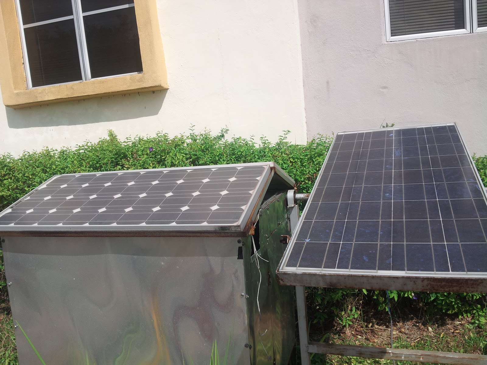
Descriptions:The SCADA (supervisory control data acquissition) oscilloscope is built using visual basic software to display the instataneous value of solar panel voltage. The SCADA program is equipped with some control buttons to start,stop and record the solar voltage. The recording time can be set through these buttons. The voltage from solar panel is hooked up to solar charge controller for charging purpose. Sealed lead acid(SLA) or AGM batteries are used as free maintainance batteries for storing energy from solar.
PIC microcontroller is used to read the voltage from solar panel using voltage divider circuit and ADC program. The PIC then translates this signal to be displayed on computer screen. The data are send through serial cable or using USB to UART converter. Two readings recorded from solar panel, one is diplayed as number via LCD, another one as image via computer screen.
Prinsip operasi
Asas prinsip operasi iaitu sistem akan memaparkan osiloskop pada komputer untuk menunjukkan voltan semasa solar panel. Satu software visual basic dibangunkan untuk menerima data voltan dari solar panel dan PIC. PIC akan membaca data ini melalui voltage divider circuit dan menghantar data tersebut ke komputer melalui serial cable dan memaparkannya pada skrin. Didalam program visual basic, pengguna boleh memilih corak paparan dan setting masing2 mengikut kehendak pengguna. Sbg contohnya membuat setting corak paparan data(jenis dot, garis, bulatan dsbnya) atau memaparkannya dalam bentuk nilai. Julat tempoh masa paparan boleh diprogram melalui visual basic samada seminit, sejam, sehari atau sebagainya. Data2 ini boleh direkod dan diletakkan dalam satu file (notepad/ excel) utk diakses oleh pengguna.
Selain dari voltan, parameter lain yg boleh dipaparkan adalah arus dan kuasa. Sistem ini dikenali sbg SCADA (supervisory control data) dan digunakan secara meluas utk membuat analisis atau pemantauan yg mana masa sbg pembolehubah utamanya.
Asas prinsip operasi iaitu sistem akan memaparkan osiloskop pada komputer untuk menunjukkan voltan semasa solar panel. Satu software visual basic dibangunkan untuk menerima data voltan dari solar panel dan PIC. PIC akan membaca data ini melalui voltage divider circuit dan menghantar data tersebut ke komputer melalui serial cable dan memaparkannya pada skrin. Didalam program visual basic, pengguna boleh memilih corak paparan dan setting masing2 mengikut kehendak pengguna. Sbg contohnya membuat setting corak paparan data(jenis dot, garis, bulatan dsbnya) atau memaparkannya dalam bentuk nilai. Julat tempoh masa paparan boleh diprogram melalui visual basic samada seminit, sejam, sehari atau sebagainya. Data2 ini boleh direkod dan diletakkan dalam satu file (notepad/ excel) utk diakses oleh pengguna.
Selain dari voltan, parameter lain yg boleh dipaparkan adalah arus dan kuasa. Sistem ini dikenali sbg SCADA (supervisory control data) dan digunakan secara meluas utk membuat analisis atau pemantauan yg mana masa sbg pembolehubah utamanya.
Subscribe to:
Posts (Atom)